Fine Bubble Diffusers Hydrodynamics: Disc vs Tube Basin Geometry Adaptation Guide
In municipal and industrial activated sludge biological wastewater treatment plants, the selection of the fine-bubble aeration geometry directly determines civil tank construction costs, underwater piping hydraulics, Standard Oxygen Transfer Efficiency (SOTE), and long-term lifecycle energy consumption. The two leading aeration technologies—Fine Bubble Disc Diffusers and Tubular / Tube Diffusers—both command significant market shares in global wastewater engineering.
However, engineering selection often falters due to an incomplete understanding of their three-dimensional hydrodynamics, bottom floor coverage limits, and hydrodynamic coupling with biological tank geometry. Installing dense disc diffusers in narrow, high-velocity oxidation ditches can introduce excessive flow resistance, while utilizing tube diffusers in deep rectangular basins without adequate floor coverage can trigger severe microbubble coalescence. Aligning diffuser hydrodynamic properties with civil basin geometry is vital for achieving optimal aeration performance.
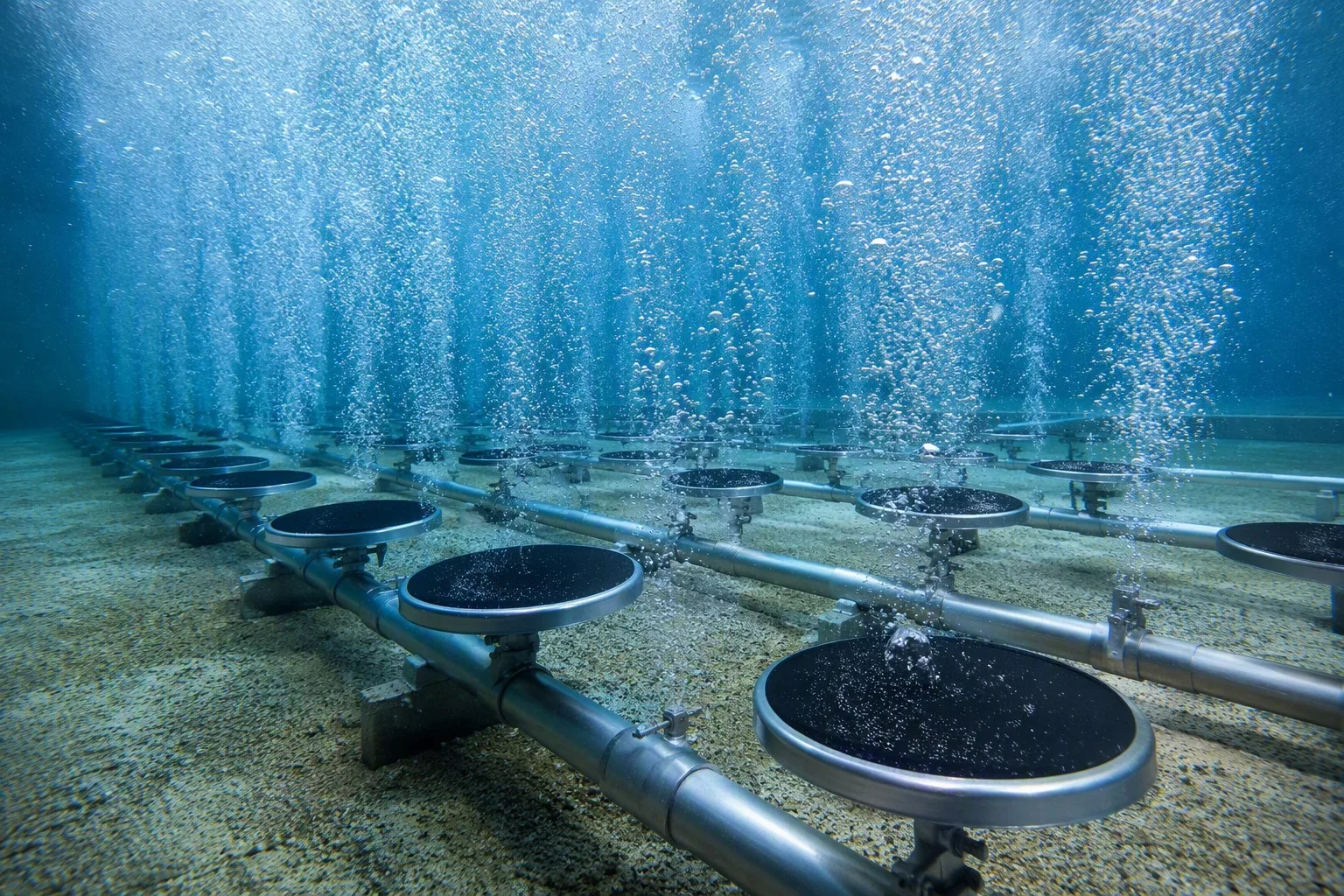
Figure 1: Fine Bubble Disc Diffusers Uniformly Distributed on Basin Floor with Microbubble Blanket
1. Geometric Profile and Microscopic Bubble Hydrodynamics
While both systems deliver fine-bubble aeration, their fluid-dynamic mass transfer mechanisms differ fundamentally:
1.1 Disc Diffusers: Two-Dimensional Horizontal Radial Field
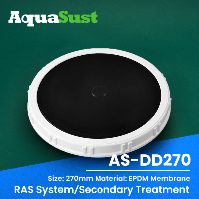
- Horizontal Discharge Plane: Circular diffusers (standard diameters: Ø215 mm, Ø260 mm, Ø300 mm / 9", 12") release bubbles from a single strict horizontal elevation datum.
- Vertical Piston-Type Flow: Compressed air expands upward from the membrane center, creating uniformly rising bubble columns. When installed in high-density grid arrays across wide floors, they establish an ideal grid-pattern hydraulic plume that maximizes interfacial contact area.
- Peak Standard Oxygen Transfer Efficiency (SOTE): Under identical submergence and air flux, disc diffusers deliver clean water SOTE of 32% to 38%, typically 2% to 4% higher in absolute efficiency than tubular designs.
1.2 Tube Diffusers: Three-Dimensional Cylindrical Flow Field
- 360° Circumferential Cylindrical Surface: Cylindrical membranes (standard Ø63 mm, Ø90 mm; lengths 500 mm to 1000 mm) wrap around rigid support tubes.
- Lateral, Downward & Scouring Action: Air discharges not only upward from the tube crown, but also laterally and downward. Bubbles emitted from the lower perimeter create localized bottom scouring micro-eddies that prevent sludge deposition in dead zones.
- Substantial Air Handling Capacity per Unit: A single 1000 mm tube diffuser handles design airflows of 6.0 to 10.0 Nm³/h (2.5 to 3.0 times that of a Ø300 disc), reducing underwater stainless steel piping branch counts by up to 60%.
2. Basin Geometry Adaptation Rules: Tank Layout vs Fluid Dynamics
Equipment geometry must integrate seamlessly with civil tank morphology:
2.1 Broad Rectangular Basins: Prioritize Disc Diffusers
For large municipal completely mixed activated sludge tanks and deep rectangular plug-flow basins:
- Optimized Floor Coverage Rate (FCR): Disc diffusers can be arranged on an axial grid spacing of 600 mm to 800 mm, achieving the optimal 12% to 20% floor coverage rate.
- Suppression of Bubble Coalescence: Wide spatial dispersion prevents microbubbles from clustering into large, inefficient gas pockets, maximizing lifecycle energy savings.
2.2 Long Plug-Flow Corridors and Oxidation Ditches: Prioritize Tube Diffusers
In narrow plug-flow channels with length-to-width ratios L/W > 5, or Carrousel / Orbal oxidation ditches with submersible mixers:
- Streamlined Parallel Alignment: Tube diffusers align parallel to horizontal bulk liquid flow (0.3–0.5 m/s). Their cylindrical profile generates over 70% lower drag coefficient than vertical disc pedestal assemblies.
- Preservation of Mixer Thrust: Prevents unnecessary dissipation of hydraulic forward velocity, eliminating sludge settling at channel bends.
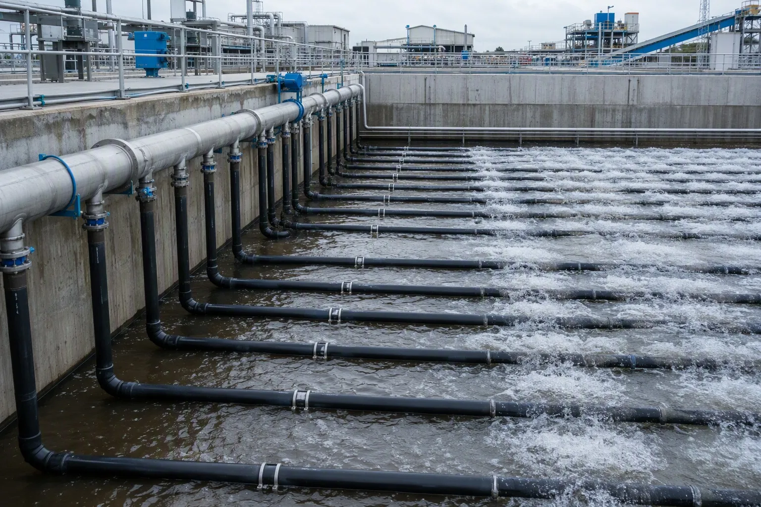
Figure 2: Industrial Wastewater Deep Corridor Biological Basin with High-Strength Tube Diffusers
3. Comprehensive Technical and Economic Comparison Matrix
| Engineering Parameter | Fine Bubble Disc Diffuser (Ø300 mm) | Fine Bubble Tube Diffuser (Ø63×1000 mm) | Selection & Design Impact |
|---|---|---|---|
| Design Airflow Capacity | 2.5 to 3.5 Nm³/h | 6.0 to 9.0 Nm³/h | Tube requires only 35%–40% the total unit count of discs |
| Standard OTE (SOTE @ 6m) | 34% to 38% (Highest OTE) | 30% to 34% (Medium-High) | Discs yield superior power savings for large municipal plants |
| Aeration Efficiency (SAE) | 4.5 to 5.5 kg O₂/kWh | 3.8 to 4.6 kg O₂/kWh | Disc delivers lowest 20-year total energy expenditure |
| Piping & Support Density | Dense (Branch spacing 700–900 mm) | Streamlined (Spacing 1200–1800 mm) | Tube cuts underwater pipe & bracket CAPEX by 30%–40% |
| Field Installation Speed | Standard (Multiple level leveling bolts) | Fast (Quick modular assembly) | Tube shortens onsite installation schedules by over 50% |
| Anti-Sludge Settling Power | Moderate (Minor dead zone under base) | Superior (Downward circumferential sweep) | Tube prevents settling of heavy, high-MLSS industrial sludge |
| Drag in Horizontal Flow | High (Obstructs bulk fluid propulsion) | Minimal (Aligned with bulk flow streamlines) | Tube diffusers are essential in oxidation ditches |
| Retrievable Grid Integration | Wide lifting frames, bulky hoisting footprint | Compact, streamlined liftable modules | Tube is preferred for non-drainable retrievable grid setups |
4. Global Engineering Specifications and Regional Practices
4.1 European Efficiency Directives (DWA Standards)
Under German DWA-M 229 guidelines, life-cycle electrical power represents the primary bid evaluation criterion. Fine-bubble disc diffusers hold over 75% market share in European municipal plants due to peak SOTE and minimized kilowatt-hour demand.
4.2 Deep Industrial Facilities in the Americas
In heavy industrial wastewater (pulp and paper, petrochemicals, textile dyeing) across North and South America, biological basins routinely operate at depths of 8.0 m to 10.0 m with MLSS exceeding 5000 mg/L. Contractors frequently deploy retrievable tube diffuser grids (AISI 316L stainless steel cores + peroxide EPDM sleeves) for rapid installation and zero-downtime overhead crane maintenance.
5. Engineering FAQ: Diffuser Hydrodynamic Selection
Q1: Why are disc diffusers rarely installed across the entire floor of oxidation ditches?
A1: Oxidation ditches rely on submersible mixers to maintain a uniform horizontal velocity of 0.3 to 0.4 m/s to keep mixed liquor in suspension. Densely distributed disc diffusers create substantial floor roughness and drag, dissipating forward mixer momentum and triggering sludge settling behind diffuser bodies. Tubular diffusers installed parallel to flow streamlines minimize drag and work synergistically with propulsion systems.
Q2: In deep aeration basins (> 8.0 m water depth), which geometry provides superior oxygen transfer?
A2: Deep basins generate high hydrostatic pressure (> 80 kPa), providing extended gas-liquid contact time as bubbles ascend. In such deep environments, the primary factor governing oxygen transfer efficiency is preventing rising microbubbles from coalescing into larger, low-surface-area bubbles. Fine bubble disc diffusers provide a wider, more uniform initial horizontal emission blanket, significantly outperforming tube diffusers in suppressing bubble coalescence.